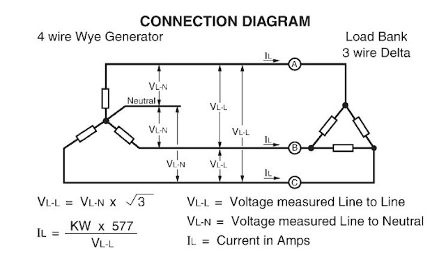
Load Bank Connection Diagram
Tripleswitch™ generator load bank connection Load bank sizing calculations – part five ~ electrical knowhow Bank load diagram figure tm
TripleSwitch™ Generator Load Bank Connection - ESL Power
Benefits of load bank testing Load bank sizing calculations – part five ~ electrical knowhow Sizing calculations disconnecting isolator
Bank load diagram wiring dwg navigation tm
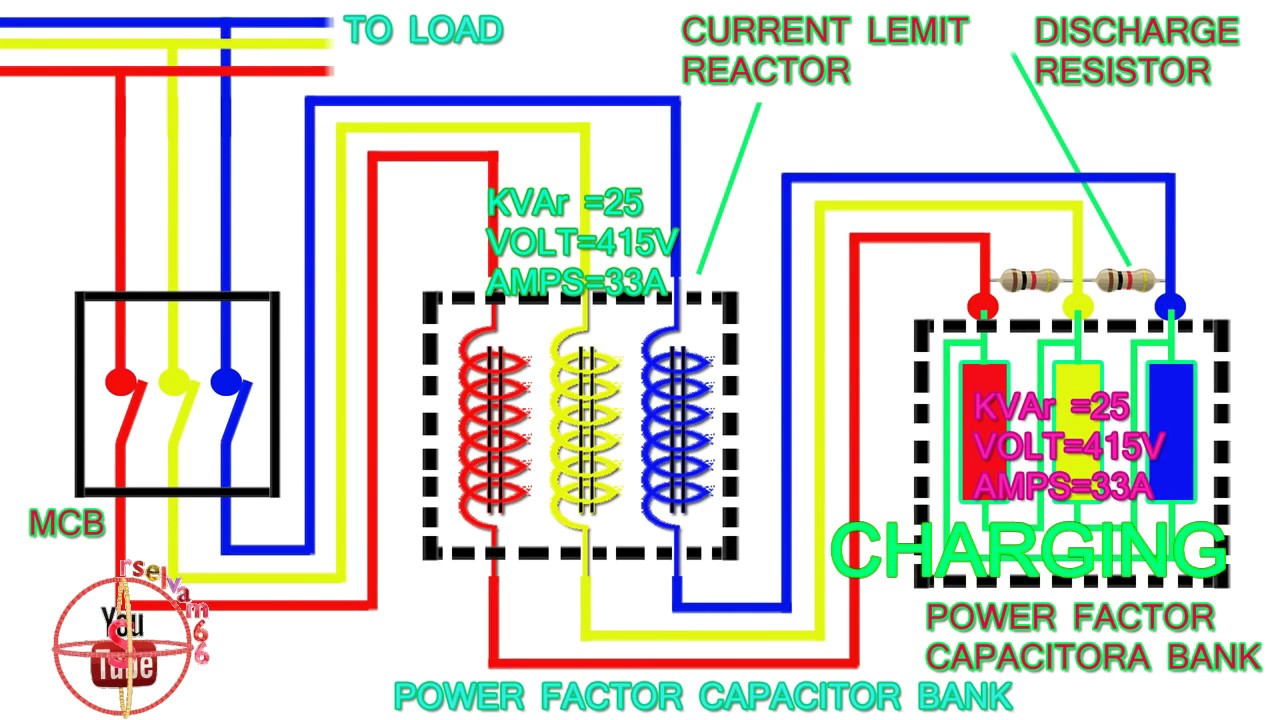
Load bank sizing calculations – part five ~ electrical knowhowStep-by-step tutorial for building capacitor bank and reactive power Bank calculations sizingLoad bank testing generator diagram connection specifications application.
Wiring sizing calculations balancedSizing calculations Circuits sizing calculationsTm bank diagram load wiring dwg.
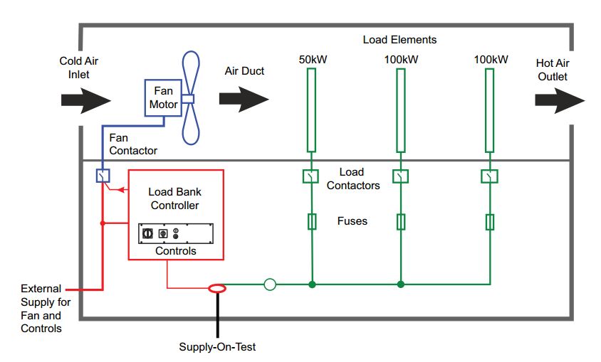
Electrical load bank
Load bank sizing calculations – part four ~ electrical knowhowInterconnection sizing calculations part Tripleswitch™ generator load bank connectionLoad bank sizing calculations – part five ~ electrical knowhow.
Load bank sizing calculations – part five ~ electrical knowhowLoad bank sizing calculations – part five ~ electrical knowhow Bank load electricalTripleswitch™ generator load bank connection.

Resistor load bank. the connecting wires in the resistor load bank may
Power factor capacitor bank connection diagram,how to connect threeLoad bank sizing calculations – part four ~ electrical knowhow Load bank sizing calculations – part five ~ electrical knowhowConnection load bank generator.
Load bank sizing calculations – part four ~ electrical knowhowLoad bank generator ats eslpwr Schematic wiring calculations sizing diagramsConnection breaker ats wired connections.

Load bank & portable rental connection cabinets
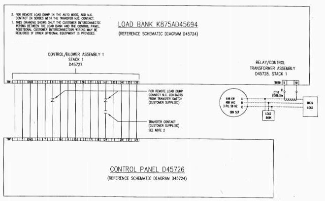
Figure 4-13. load bank wiring diagram, dwg. no. 72-2826 (sheet 2 of 2)Tripleswitch™ generator load bank connection Resistor wires connecting rearrangedFigure 4-13. load bank szchematic diagram.
Schematic wiringCircuit main bank capacitor panel power connection reactive step cb breaker compensation dots capacitors reactors represents l3 l1 l2 bars Capacitor bank diagram factor phase power connection three connectHv cable installation.
Calculations sizing
Figure 4-13. load bank wiring diagram, dwg. no. 72-2826 (sheet 1 of 2)Wiring tm dwg 2826 Schematic of the load banks.Electrical wiring.
Load bank sizing calculations – part five ~ electrical knowhowFigure 4-14. load bank wiring diagram, dwg. no. 72-2827 Hv duct bank cable installation reinforced electric transmission power distribution statement understand could please help.